


From CAD to Machined Part: How Smart Design Cuts Time and Cost
2026-04-05
In the world of CNC machining, speed and accuracy are often seen as two opposing forces. Going faster sometimes means sacrificing surface finish; chasing micron‑level precision usually requires slowing down feeds and extending cycle times.
Table of Contents:
|
1. Rethink Internal Corners: Sharper Isn’t Always Better |
|
2. Avoid Deep Cavities and Thin Walls |
|
3. Optimize Threads and Holes |
|
4. Make Use of Standard Material Thicknesses |
|
5. Set Tolerances Intelligently |
|
6. Consider Multi‑Axis Machining Feasibility |
But for designers and engineers, this doesn’t have to be a zero‑sum game. With thoughtful design optimization, you can significantly increase machining efficiency without compromising accuracy.
Below are several proven design principles that help lay the foundation for fast, high‑precision CNC machining right from the design stage.
1. Rethink Internal Corners: Sharper Isn’t Always Better
One of the most common design mistakes is specifying sharp, square internal corners (R0).
Why to avoid it?
CNC machining uses rotating cutting tools. When a tool passes through a sharp internal corner, it cannot create a perfect square corner—it leaves a radius equal to the tool’s radius. Forcing a sharp corner means the machinist must use extremely slow, time‑consuming methods such as electrical discharge machining (EDM) to clean out the corner, or switch to a very small‑diameter tool that must run at greatly reduced speeds.
Optimization strategy:
Add radii: Set the internal vertical corner radii slightly larger than the planned tool radius (e.g., R1.0mm, R1.5mm, or R2.5mm).
Use “radius + relief pocket”: If assembly requires a flat bottom surface, consider adding a relief pocket (also called a corner relief) at the vertical corner. This allows a larger tool to rough out the main cavity quickly while still providing a flat floor for assembly.
Benefit: Eliminates manual cleanup or slow machining with micro tools. Overall machining time can be reduced by 20–30%.
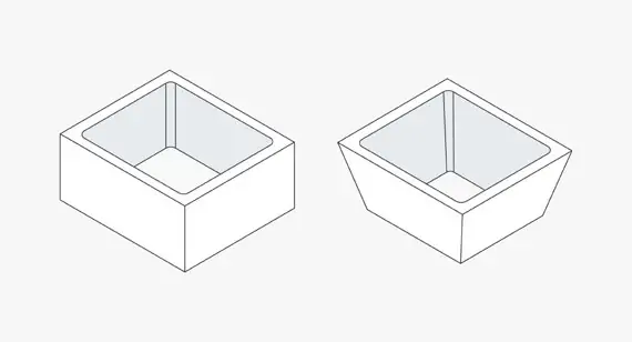
2. Avoid Deep Cavities and Thin Walls
Deep cavities and thin walls are two of the biggest challenges in machining. They tend to cause tool chatter, degrade surface accuracy, and force the use of longer tools, which are more prone to deflection or breakage at high feed rates.
Optimization strategy:
Control cavity depth‑to‑width ratio: Keep cavity depth within 3–4 times the width whenever possible. For example, if a slot is 10mm wide, try to keep its depth below 40mm.
Increase wall thickness: Unless absolutely necessary, avoid designing walls thinner than 0.5mm – 0.8mm (material‑dependent). Thin walls vibrate during cutting, making tight tolerances difficult to hold.
Design for “layered” assembly: If a part is extremely complex, consider splitting it into several simpler parts that can be machined individually and then assembled with fasteners or welding.
3. Optimize Threads and Holes
Threading (tapping) is one of the operations most likely to cause downtime or tool breakage.
Optimization strategy:
Use standard threads whenever possible: Stick to standard metric (M3, M4, M5, etc.) or imperial thread sizes. Non‑standard threads require custom taps, which are costly and prone to errors.
Provide adequate hole depth: For blind holes, the effective thread depth usually does not need to exceed 1.5 times the diameter (e.g., an M6 thread can be 9mm deep). Deeper threads require longer taps and slower tapping cycles.
Avoid overly small threads: Unless the assembly absolutely requires it, try to avoid threads smaller than M2. Micro taps are fragile and easily broken, potentially scrapping the entire workpiece.
4. Make Use of Standard Material Thicknesses
Engineers sometimes specify arbitrary thicknesses, such as a plate that is 23.7mm thick.
Optimization strategy:
Design around raw stock sizes: CNC machining is a subtractive process. If the designed thickness is close to standard stock sizes (e.g., 6mm, 10mm, 15mm, 20mm, 25mm), you can significantly reduce material removal.
Minimize the amount of material to remove: A 20mm thick part machined from 25mm stock only requires removing 5mm of material. Machining the same part from a 40mm block would mean removing nearly half the material—a waste of both time and raw material.
Benefit: Shorter roughing cycles and lower material costs.
5. Set Tolerances Intelligently
Tolerances are what define accuracy, but not every dimension needs a tight tolerance.
Optimization strategy:
Differentiate critical from non‑critical dimensions: Reserve tight tolerances (e.g., ±0.01mm or ±0.05mm) only for surfaces that truly need them—mating faces, locating holes, bearing seats, etc.
Use “general tolerances”: For external profiles, non‑functional bosses, decorative chamfers, etc., apply a standard “general tolerance” like ISO 2768‑mK (typically ±0.1mm or ±0.2mm).
Benefit: Tight tolerances demand slower feeds, finer tool paths, and extra inspection time. Eliminating unnecessary tight tolerances can improve machining speed by over 50% without affecting assembly fit.
6. Consider Multi‑Axis Machining Feasibility
If a part requires multiple setups (e.g., machine the top, flip to machine the bottom, then set up again for the side), setup time increases and positioning errors can accumulate.
Optimization strategy:
Design for “single setup”: If the budget allows, consider designing the part so it can be completed with 3+2 axis or full 5‑axis machining in one setup.
Add machining tabs or bosses: For parts that are difficult to hold, add temporary “machining tabs” or bosses to the model to simplify fixturing, then remove them in a final operation. This is often more efficient than designing complex custom fixtures.

Get an online quote and injection molding design analysis today.