


I. Suggested Content Structure
Part 1: Design Phase – Design Guidelines for CNC Machining
This section guides designers on how to create drawings that are "machinable, low-cost, and high-quality."
1. Geometric Feature Design
Internal Corners (Pockets): Must specify the use of fillets/radii, with a radius greater than or equal to the cutter radius used. Provide recommended values (e.g., R1, R2).
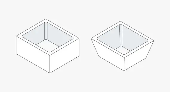
Pocket Depth: Specify reasonable depth-to-width ratios (e.g., general milling depth should not exceed 4-5 times the cutter diameter). Avoid overly deep pockets causing tool chatter or breakage.
Thin Walls: Define minimum wall thickness (e.g., aluminum ≥1mm, steel ≥2mm) to prevent deformation during machining.
Threads: Standardize thread callouts (e.g., M6×1). Specify if through or blind. Recommend threaded inserts over direct tapping where applicable, and provide recommended tap drill depths.
Text & Engraving: Recommend using single-stroke fonts. Define minimum character height and line width (e.g., height >3mm, width >0.3mm).
2. Tolerances & Fits
Basic Principle: Emphasize "loose tolerances where possible, tight tolerances only for critical features." Use economical tolerances for non-critical faces (e.g., ±0.1mm or ±0.25mm).
Critical Features: Clearly specify precise tolerances (e.g., H7/g6) and geometric tolerances (e.g., cylindricity, concentricity) for bearing seats, gear meshing surfaces, etc.
Explanation: Explain how overly tight tolerances significantly increase costs (requiring more precise machines, more inspection, lower yield).
3. Material Selection
List common CNC materials and their properties:
Aluminum Alloys (e.g., 6061, 7075): Lightweight, easy to machine, cost-effective. Suitable for most parts.
Steels (e.g., Mild Steel, 1045, Stainless 304/316): High strength, wear-resistant, but more difficult to machine with higher tool wear.
Plastics (e.g., POM, Nylon, PEEK): Insulating, dampening. Note thermal deformation and elasticity.
Provide material selection guidance: Analyze from perspectives of function (strength, wear, corrosion resistance), manufacturability, cost, and post-processing (anodizing, heat treatment).

Part 2: Engineering Phase – Process Planning from Drawing to Part
This section is for process engineers or programmers, translating design into executable manufacturing instructions.
1. Process Route Planning
Operation Sequencing: E.g., "Cut stock → Rough mill 6 sides → Finish mill reference faces → Drill/Tap holes → Finish mill pockets → Deburr → Inspection."
Workholding Strategy: Design or select fixtures (vises, fixture plates, custom fixtures). Analyze how to minimize setups and ensure consistent datum references.
Machining Order Principles: Follow "Rough before finish, faces before holes, primary before secondary."
2. Tooling & Parameter Selection
Tooling List: Specify tool type (end mill, ball nose, drill, tap), diameter, flute length, and material (carbide, HSS) for each operation.
Cutting Parameters: Provide recommended Cutting Speed (Vc), Feed per Tooth (fz), Axial Depth of Cut (ap), Radial Depth of Cut (ae). Use tables for different materials.
*Example (Carbide End Mill for Aluminum): Vc=200-300 m/min, fz=0.05-0.1 mm/tooth, ap=0.5D, ae=0.1D*
3. CNC Programming Key Points
Coordinate Systems: Define workpiece coordinate system (G54-G59) setup and use of edge finders/touch probes.
Toolpath Strategies:
Pocketing: Use helical or ramp entry to avoid plunging.
Contouring: Mention climb vs. conventional milling (climb recommended for finishing).
Drilling Cycles: Use proper cycles (G81/G82/G83). Use peck drilling (G83) for deep holes to ensure chip evacuation.
Safety & Efficiency: Include clearance heights, retract planes, and use of subprograms/loops for code efficiency.
Part 3: Quality Control & Inspection
1. On-Machine Inspection: Use machine touch probes for preliminary checks of critical dimensions.
2. Final Inspection Methods & Tools:
General Dimensions: Calipers, micrometers.
Geometric Tolerances: Dial indicators, CMM (Coordinate Measuring Machine).
Surface Finish: Surface roughness tester.
3. Documentation: Inspection reports, First Article Inspection (FAI) reports.
Get A Qoute
II. Documentation Writing Tips & Format
1. Use Visuals, Charts, and Diagrams:
Use 3D model screenshots, 2D drawing callouts for key features.
Use flowcharts for process routes.
Use tables to compare material properties, tooling parameters.
2. Standardization & Templates:
Create standard CNC Design Checklist, Process Planning Sheet, Tooling Parameter Sheet.
Unify terminology (e.g., "roughing," "finishing," "corner cleaning").
3.Version Control:
Implement strict version control for design drawings and NC programs to ensure the latest files are used on the shop floor.
4. Include "Notes" or "Lessons Learned":
E.g., "When machining stainless steel, use tools with a large positive rake angle and ensure ample coolant to control work hardening."
"This long narrow slot is prone to deformation. Recommend finishing it in the final operation."
1. High-Speed Machining (HSM) & 5-Axis Machining: Strategies like small step-downs, high feed rates, full climb milling; benefits of 5-axis positioning and simultaneous machining.
2. Strategies for Difficult-to-Machine Materials (e.g., Titanium, Inconel): Low RPM, high DOC, maintaining constant chip load.
3. Machining Simulation & Optimization: Using software like VERICUT for collision checking and toolpath optimization to reduce trial cuts.
4. Automation & Digitalization: Integration with MES systems for automatic program dispatch and production data collection."a

Full-Process Optimization from Concept to Finished Product
1. Cost Engineering & Value Analysis
This bridges design and business, crucial for decision-makers.
1.1 Cost Breakdown Model:
Material Cost: Optimizing nesting (CAM programming) to minimize waste. Can standard stock be used instead of a solid block?
Machining Time Cost: Establish a "machine hourly rate." Analyze how optimized toolpaths (e.g., HSM, trochoidal milling) reduce cycle time.
Tooling Cost: Analyze the relationship between tool life and parameters. Compare high-cost/long-life tools vs. low-cost/frequent-change strategies with a cost-per-part model.
1.2 Secondary Operation Cost: Fixturing time, inspection, and post-processing (e.g., anodizing).
Design-for-Cost Optimization:
Part Consolidation: How can multiple components be cleverly designed as one CNC part, eliminating assembly and inventory costs?
The "Good Enough" Philosophy: Case studies showing how relaxing non-critical surface finish (e.g., Ra1.6 vs. Ra0.8) or tolerance (±0.05mm vs. ±0.02mm) dramatically reduces cost.
Alternative Manufacturing Comparison: Comparative cost analysis charts: CNC Machining vs. 3D Printing (Metal/Plastic) vs. Sheet Metal Fabrication vs. Die Casting for low-volume vs. medium-volume production.a

2. Application-Specific Design & Engineering
Design is meaningless without context.
2.1 Aerospace & Defense:
Lightweighting: Combining topology optimization with CNC machining. Designing conformal cooling channels.
Material Challenges: Strategies for machining titanium, high-strength aluminum to prevent burn and stress distortion.
Traceability & Certification: Requirements for full traceability of material batch, machining parameters, and tooling records.
2.2 Medical Devices:
Biocompatible Materials: Machining considerations for titanium, cobalt-chrome, PEEK.
Surface Finish & Cleanability: Designing crevice-free, sterilizable geometries. Polishing process selection.
Micro-Machining: Programming and process challenges with micro-tools (<1mm).
2.3 Automotive & Molds:
Prototyping & Low-Volume: Rapid workflow from CAD to functional CNC prototypes.
Mold & Die Making: Electrode design for EDM collaboration. Application of 5-axis machining for complex cavities.
3. Collaborative Design & Digital Workflow
The nervous system of modern manufacturing.
3.1 The Digital Thread from CAD to G-Code:
Seamless Data Transfer: Using neutral formats (e.g., STEP) to prevent data loss between CAD and CAM systems.
Model-Based Definition (MBD): Promoting MBD - embedding all dimensions, tolerances (GD&T), and notes within the 3D model as the single source of truth.
CAM Automation: Feature-Based Machining (FBM) and template-based programming for automatic, optimized toolpath generation on standard features (holes, pockets, threads).
3.2 Integration with Simulation & Digital Twin:
Process Simulation: Using software for toolpath verification, material removal simulation, and machine collision checking.
Virtual Commissioning: Testing CNC programs within a digital twin environment to verify logic and cycle time.
Get A Qoute
4. Emerging Technologies & Trends
Demonstrates industry foresight.
4.1 Hybrid Additive-Subtractive Manufacturing:
Designing for "print then machine" workflows (e.g., DED + CNC). Planning the transition interface.
4.2 AI & Machine Learning in CNC:
Adaptive Machining: Real-time sensor monitoring of cutting forces/vibration, with AI adjusting feed/speed for optimized, unattended machining.
Predictive Maintenance: Analyzing spindle load, tool vibration to predict wear and machine failure.
4.3 Automation & Lights-Out Manufacturing:
Designing parts for automated fixturing (standardized datums, minimal custom jigs).
Integrating pallet systems with CNC for 24/7 production.
5. Sustainable Manufacturing & Green Engineering
Aligns with ESG principles and enhances brand value.
Material & Energy Efficiency:
Lightweight design as a driver for energy savings.
Analyzing the environmental impact of cooling methods (flood, MQL, cryogenic).
Best practices for cutting fluid management and recycling.
Tool Lifecycle Management:
Feasibility analysis of tool re-grinding and re-coating.
Processes for recycling scrap carbide tools.
6. Knowledge Management & Training Systems
Ensures long-term organizational competency.
6.1 Defect Library & Solution Database:
Create a visual "failure mode" library. Example:
Problem: Chatter marks on surface.
Root Causes: Excessive tool overhang, poor workpiece clamping, aggressive parameters, worn tool.
Solutions: Reduce overhang, check fixture, adjust feed/speed, replace tool.
6.2 Internal Technical Case Studies:
Regularly document post-mortems of significant parts (especially challenging, successful, or cost-optimized), capturing the complete journey from design to delivery as institutional knowledge.
Get A Qoute

Get an online quote and injection molding design analysis today.